Inleiding
In februari dit jaar had ik reeds een dualband vertical gemaakt voor 4 en 6 meter.
Deze heb ik nu uitgebreid met de 2 meter band.
Dit door toevoeging van een staafje 4mm dik aluminium op 4,3 cm van de
6 meter dipool.
De resultaten zijn goed te noemen en hij is simpel te maken. Op alle banden is de swr ok.
Uitvoering
Het ontwerp is gebaseerd op de DK7ZB triband antenne.
Benodigd is:
-- 5 buisjes 6mm diam. 1.00 m lang
-- 3 buisjes 8mm diam. 1.00 m lang.
-- 50 cm rvs 3mm diam. draadstang
-- 30 cm rvs 4mm diam. draadstang
-- 2 rvs bouten en moeren 4mm diam., 12mm lang
-- 1 rvs bout en moer 4mm diam., 25mm lang
-- stukje snijplank (bijv. ikea)
-- wat moertjes en vleugelmoeren.
-- 1 meter pvc electrabuis 16 mm diam.
Door wat te spelen met de onderlinge afstanden is de SWR op 2 en 4 meter < 1,2. Op 6 m ca. 1,5.
Het is een open sleeve principe. Proefondervindelijk bleek een extra stukje
van 6cm onderaan de 6 meter dipool een betere SWR op 6m te geven.
Het bovenste deel van de 'mast' beïnvloedt nl. de stralers.
De gain op 2m is zelfs nog 3,9 dBd. Dit komt doordat de brede 6 meter dipool als het ware meewerkt en deze is ook resonant op 2m. Dit is duidelijk merkbaar maar er zijn geen scherpe minima in het diagram.
De afstand van de mast tot de 6 meter dipool is 35cm.


buis.
De elementen zijn voor één meter van 8mm en uiteindes van 6mm alu buis.
Deze zitten in elkaar geklemd.
De elementen zijn op een nylon plankje bevestigd met 3mm rvs draadstang
U-tjes.
Het beste is trouwens het nylon plaatje uit één stuk te maken.
I.v.m. minimale windvang heb ik deze klein gelaten.
Ik heb ze overigens gemaakt van een snijplank van IKEA a € 1,49..
Voeding vindt plaats op de 6 meter open dipool via een mantelstroom-filter.
Het onderste pvc steun-buisje is belangrijk i.v.m. de steun, zodat de antenne niet doorzakt.
Alle plastic buisjes kunnen van electra PVC buis gemaakt worden.
(Zelf heb ik ook wat dunner materiaal gebruikt, zie foto's)
In de PVC buisje zijn gaten geboord zodat ze net goed klemmen.
Hierna vastgelijmd.
De antenne is niet zuiver rondstralend; met name op de 2 meter band is er
een maximum aan de zijde waar de elementen bevestigd zijn. Maar de verschillen per richting zijn maximaal zo'n 3 dB.

English:
Here are the details for the vertical for 2, 4 and 6 meter band.It is based on the DK7ZB triband yagi antenna . But now only the
dipoles are used . The sizes differ of course somewhat.
It is also an open sleeve principle. Experimentally it came out that an extra piece of 10 cm tube
on the bottom of the 6 m dipole improved the SWR. (Compared with a horizontal version)
That's because the mast and coax cable are somewhat acting as a director.
This tri band appeared to be slightly better than an end fed half wave on 6 m.
The distance from the mast to the 4 meter dipole is 25cm .
I built a lightweight version . But more stronger design also will work. The small 'boom' I made of 15x15mm square tube. However 20x20 mm: no problem of course.
The 6 m dipole is for one meter of 8 mm and the ends are of 6 mm tube. The 4 meter rod is for 40 cm of 8 mm and the ends of 6 mm tube.
These are clamped together . The 2 meter band rod is made of 4 mm massive aluminium.
But one can also feel free to create everything from 10 mm tube . That certainly will work if they are made about 1% shorter.
The elements are mounted on a board with nylon 3 mm stainless steel wire U- rods,
For minimum windload I left the boards small.
Here I have made it from a 8 mm cutting board.
Feeding takes place on the 6 meter dipole by means of a shoke filter.
The lower PVC tube is important for support and made of 5/8 electricity pipe.
It is better to use gray pipe ( Hostalite )
This includes holes drilled 6mm and clamped over the elements.
The SWR on all bands is lower then 1.4.
The antenna is not purely omnidirectional ; in particular at 6 meters and 2 meters , there is
a maximum on the side where the elements are fixed . But the differences in each direction are maximum up to about 3 dB .
Alignment:
It's interesting how this antenna can be aligned. Best is about 2 m above the ground.
In three steps:
In three steps:
First only mount the 6 m dipole and all plastic support tubes. Do not the drill the second holes in them before the 2 and 4 m dipoles are attached.
SWR on 6 m should be below 1.4 directly. Then start with positioning the 4 m dipole. 9 cm distance should be ok if it's made of 6 mm tube. Thicker will need more distance.
The further the distance the higher the impedance. The length is the 'tuning'. Check for best SWR.
If there is no position were the SWR is low then the rod is to long or to short. If for example the SWR can be made ok on 68 Mhz, that means that it has to be shortened and vice versa.
Drill holes in the support tubes on the right position and mount the rod by shifting it through the supports and in the middle.
After that, the same procedure has to be followed with the 2 m rod. 100 cm length should be ok for 4 mm tube. 99 cm for 6 mm.
Results:
The antenna is in use know (april 2014) for two years in still working well on all bands. I made several sporadic-E QSO's on 4 and 6 m.
It is noteworthy that on 2 m the performance is still better then on the Diamond X50. This is because the wide 6 m dipole is almost resonant and picking up 2 meter energy also and the small 2 m dipole is only acting as a tuner and makes the SWR low.
Giving 3.5 dBd gain.
Here the antenna is mounted free turning from the wind-direction . If wind is strong it's acting as a banner.)
But by doing this it has survived several storms.)
Good luck if you want to built it too !
 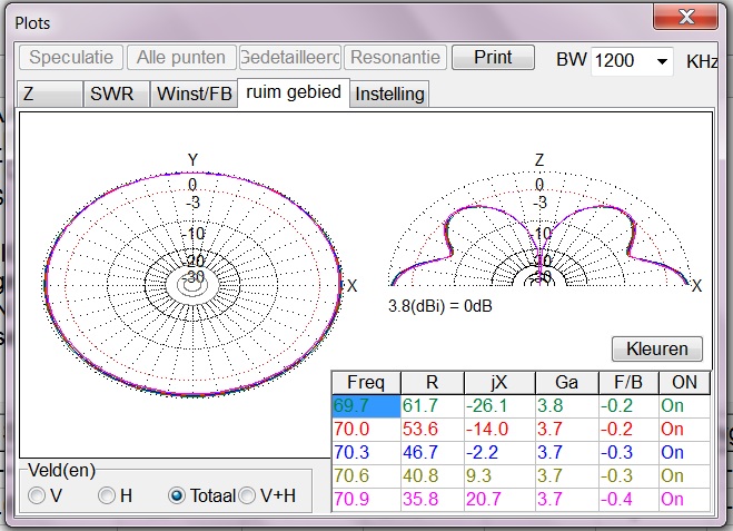 |
| Plot 70 mhz |
 |
| SWR Plot 50 mhz. In de praktijk was het iets beter . |
 |
| SWR 70 mhz |
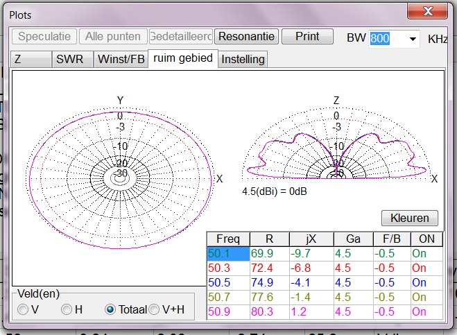 |
| Plot 50 mhz boven realground 10m |
 |
| Realground: De antenne heeft een gain van 3,9 dBd in één richting en geen scherpe minima. |