woensdag 20 november 2019

Dual band matching networks for VHF endfed vertical antennas

Recently I succeeded in designing a dual band matching network for a 70 and 144 Mhz 1/2 wave endfed vertical.
On both bands the impedance is high. About 300 ohm on 2m and 600 ohm on 4 meter band.

After this, I decided to design networks for a 28 + 50 vertical with trap.

I used the Smith chart program of Prof. Fritz Dellsperger.

Here are some results;

28 + 50 Mhz, both transformed from 50 to 800 ohm


28 + 50 Mhz, both transformed from 50 to 200 ohm


28 + 50 Mhz, both transformed from 200 to 800 ohm


50 + 70 Mhz, both transformed from 50 to 500 ohm


donderdag 14 november 2019

Dual band vertical antenna for 2 and 4 meter band (70 and 145 Mhz )

Because a 2 and 4 meter vertical is hard to find , I decided to built one.
It's a 1/2 wave with trap.
For both frequencies the impedance is high. About 500 ohms for 2m and 800 ohms
for 4 m.

This can be matched with the right dual band matching network. Consisting of two coils and two C's.
I designed it with a smith chart program. Although you have to retune it somewhat in the
' real world' . First I used plain coils, later isolated.

There is a 5.6 pf and 2.2 and 5.6 pf in parallel. Take at least 500 V types.


This is the circuit, designed with smith chart program.
2 meter section is 89 cm; 4m section 67 cm.

Description

The first (2m) part is 89 cm long. The lower part is of 12.5 mm alu rod and 65 cm long. It's attached with 2 pieces of 18 mm cutting board. In this tube comes a 30 cm long 10 mm tube that can be tuned with a hose clamp.
Then follows the trap. It consists of a 10 mm int. diameter PE tube. external 12 mm. The tubes are attached which 3 mm bolds and nuts. The coil consists of 4 windings, int. diameter 12.5 mm. Attached with cable lugs.
The parallel C is of 6 cm RG-58. When you tune it, start with about 8 cm and then cut it untill there is resonance. This coil is the easiest. For tuning connect it with a high impedance 145 signal, and there shouldn' t be any influence.
Above is 67 cm of 10 mm tube for the 4m band. Because the trap extends this part, it seems less then a half wave.

The dual band matching section consists of 2 coils and 2 C's. When they have the right values, it tunes both bands. It took a lot of  'try and error' to find it out. I also used a 1;4 transformer with FT140-61 toroidand transformed both bands to 200 ohm. To transform this to 500-800 ohm is less critical. However you need large coils (500 and 650 nH)

Trap with 200 nH coil and 6 pf RG-58


Here's the 3 pf fine tuning C
Results

It works fine. SWR is below 1.3 on both bands.

Indoor testing. Sorry for the French..
Determining coils and c' s

Testing with FT140-61 coil, 2.5 windings. This gives larger bandwidth and the step up coils have to be larger; 500 nh and 650 nH. But more complicated.


indoor testing..


vrijdag 11 oktober 2019

Tunen en resultaten met de varicap FM yagi

De verbeterde varicap yagi heb ik nu drie maanden in gebruik met goede resultaten.
Met name het minimaliseren van storende signalen gaat beter.

Het tunen; de 3 knoppen volgen in hoofdlijn de frequentie; Dit is de uitgangspositie. Dus voor 88 Mhz staan ze allen linksom.
Voor 108 Mhz bijna rechtsom. Bij 97 Mhz  allen in de middenstand.
Wanneer getund is op een frequentie, is het diagram het meest gericht. Dat betekent dat alle signalen uit andere richting verzwakt worden.
Getuned op 88 Mhz , is de ontvangst hoog in de band slecht. Omgekeerd ook.
Tunen van de dipool heeft de meeste effect op het S getal. Echter betekent dit niet automatisch dat de ontvangst dan het beste is.
Met de overvolle band is het minimaliseren van stations op een frequentie vaak een uitkomst.

O.a.op de volgende frequenties heb ik duidelijk verbetering;

88,5 Mhz BRF Luik - 179 km. Vroeger nauwelijks ontvangst, nu het beste signaal uit Luik.
90,5 Mhz Vivacite Luik - 179 km. Het onderdrukken van 90,4 Mhz Ruurlo gaat veel beter.
91,2 Mhz Brussel  - 182 km. Is nu een schone frequentie.
94,7 Mhz Lille  - 300 km. Vroeger nauwelijks uit te filteren ivm co-channel op NPO4 op 27 km
                                            afstand.Gaat nu wel, door nauwkeurig te tunen.
96,0 Mhz Ochsenkopf 474 km. Is schone frequentie. Zowat iedere dag te horen.
97,0 Mhz Hosingen 239 km. Vaak piratenstoring, maar wanneer niet te sterk, goed weg te filteren.
98,8 Mhz Reims 369 km . Beter; op de achterkant het sterkere Osnabruck.
103,9 Mhz -Naestved.  517 km. Zowat geen co-channel storing meer. Ook vaak te horen.


Door reflector en director precies te tunen, zijn storende signalen vrijwel weg te nullen.
De stand van de potmeters kan daarbij heel verrassend zijn.

Het grappige is dat op sommige frequenties wel 3 , soms wel 4 stations eruit te halen zijn.

Tussen ca. 93 en 101 Mhz kan ook op de achterkant ontvangen worden. Dus reflector wordt director en omgekeerd. Handig om even snel te kijken of daar condities zijn, zonder rotorswitch.
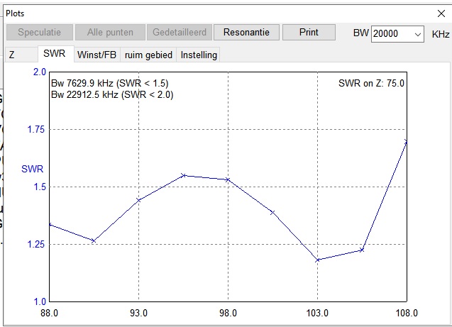
Eenmaal getuned is de bandbreedte globaal zo'n 4 a 6 Mhz. Dus er hoeft niet bij elke verstemming getuned te worden.
Verder is bij tunen op maximum signaal de openingshoek vrij klein. Ook dat geeft een relatieve verzwakking van signalen uit andere richtingen.

In de zomer veel ES DX ontvangen o.a. Algerije, Marokko, Griekenland, Albanie.

Ik heb nog een vergelijking gedaan met de zenders uit Langenberg, tussen de 5 el. K6sti.
Ook een goede antenne. Ontvanger R-7000 Icom. Antenne 5m hoog.
                            Varicap yagi              K6STI
93,3mhz Kleef     S 8,9                         S   7,3
95,1 mhz               S 7,5                        S   7,5
96,5 mhz               S 6,5                       S    6,0
99,2 mhz                S 7,5                       S  6,8
103,3 mhz             S 9,5                       S   8,5
106,7 mhz             S 8,5                        S   9,0

Om de aanpassing te verbeteren, heb nog 1 varicap toegevoegd. Deze zit direct van de coax aansluiting naar de dipool. Aan de andere kant van de varicap een spoeltje van 100 nH naar massa. Een LC combinatie dus. Hierbij bereik ik meest bovenin de band 1 s punt meer. Daar is de impedantie het hoogst, door de lange dipool (in labda's.) Onderin de band is er nauwelijks verbetering.

dinsdag 10 september 2019

Dipool antenne voor 4 en 6 meter band 'dubbel dip'

Door het juiste LC netwerkje (2x C en een L)  te plaatsen is het mogelijk een dipool antenne voor 2 frequenties te gebruiken. Als voorbeeld een 50 Mhz band dipool, die ook op 70 Mhz bruikbaar is en daar een goede SWR heeft. zelfs heeft deze daar 0,4 db gain.
Een dipool van 2.80 m heeft op 50 Mhz een impedantie van ca. 70 ohm. Op 70,3 Mhz is dit 285 + J 290 ohm. Beide frequenties moeten omhoog worden getransformeerd.

Door in MMANA te puzzelen, kwam ik op deze richtwaardes uit.


De waardes van alle 3 componenten komen wel vrij nauwkeurig. Ook de spoel. Daarom heb ik in de testopstelling afstembare C's toegepast. in de praktijk zijn er aansluitdraden en deze hebben ook hun zelfinductie.
Eenmaal afgestemd is het best vrij breedbandig. Er ontstaat wel een redelijk hoge Q dus de schakeling is minder geschikt voor hoge vermogens.
Bij de testen heb ik een mantelstroom balun van RG-174 toegepast.


Men kan stellen dat dit principe werkt zolang de 2e frequentie 10 tot 30 procent hoger ligt dan de laagste.
Zo ook op de FM band.
Dit geldt voor een dipool van 1.62 m breed. De spoel is 0,47 uH. In serie hiermee 8 pf. Dan naar massa 14 pf.

zaterdag 6 juli 2019

Varactor tuned FM yagi 3 elements with open dipole


Om de in 2016 gebouwde yagi te verbeteren, besloot ik een open dipool te proberen. 

Een open dipool zou het voordeel moeten hebben van een lagere impedantie en, zoals ik hoopte, betere prestaties.

Omdat deze relatief breed is, neemt de impedantie toe.


Na simulaties in MMANA bleek dat twee keer 81 cm een ​​goede lengte zou zijn.

Ik heb tests gedaan maar het leek erop dat de laagste frequenties, 88 Mhz, niet binnen bereik waren.

Op 2 juli ontving ik een Italiaans VOR baken op 116,96 Mhz en kon zelfs de dipool worden afgesteld op 118 Mhz.

Hierop besloot ik de dipool te verlengen tot 2x 90 cm met een 8mm buis en dit was een goede keuze.

Dergelijke lengtes lijken misschien veel te lang, maar dat is niet het geval.

Deze open dipool heeft een impedantie van 104,4 ohm bij 88 Mhz en bij 266 ohm bij 108 Mhz + een inductief deel.

De varactors stemmen deze reactantie echter probleemloos weg.


Het toevoegen van een afgestemde reflector en director geeft een verlaging van 2 a 3 maal de dipoolimpedantie, dus dit zou een mooie aansluitwaarde moeten geven.

Een andere verbetering was het gebruik van een choke met 8 windingen RG316-kabel, in plaats van RG58.

Dit gaf een betere onderdrukking van verticale signalen.


De dipool heeft twee varactors voor de balans, maar dit is geen probleem. Uiteraard is de maximum capaciteit dan slechts de helft. Maar dat bleek geen probleem.


De resultaten zijn zeer positief.


Voor overige details zie op mijn blog van 2016.

English:

After considering improvements on the yagi built  in 2016 , I decided to try an open dipole. One could mention it a steerable yagi or ESPAR antenna. But they are mosttimes designed for microwave use.
An open dipole should have the advantage of a lower impedance and, as I hoped, a better performance. Because it is relativily wide, impedance increases.
After simulations in MMANA it appeared that two times 81 cm should be a good length.
I did tests but it seemed that the lowest frequencies, 88 Mhz, were not in reach.
On july 2nd I received an Italian VOR beacon on 116,96 Mhz and the dipole could even be tuned
to a maximum of 118 Mhz.
Because of this I decided to extend the dipole to 90 cm with some 8mm tube and this was a good choice.
Such lengths may seem much too long but this isn't the case.
The sole dipole shows an impedance of 104,4 ohm at 88 Mhz and at 266 ohm at 108 Mhz.
The varactors tune out the reactance without problems.

Adding a tuned reflector and director gives a reduction of 2 or 3 times the dipole impedance, so this should be a nice value.
An another improvement was using a choke with 8 turns of RG316 cable, instead of RG58.
This gave better suppression of vertical signals.

The dipole needs to have two varactors for balance but this isn't a problem. Of course the maximum
capacity is only half. But it wasn't a problem.

The results are very positive.

For other details see at my blog of 2016.


Principle schematic with BB640 varactors


All elements are made of 6 mm diameter tube. Tuning is done with 3x 100 k potmeters on 30 V dc.
The minus poles of varactors are connected to the boom, which is connected to the outer coax pole.


Tuning the dipole can be improved by placing a third varactor in series together with a coil of 250 nH to minus pool . Especially for highest frequencies it gives a larger signal.


                                                   Tuning unit for 4x 30 V DC .,              


                                     Circuit at reflector and directors.


                                       A distance of 0.15 wl gives a good F/B ratio.

                                                The power supply with current Limiting.

The power supply.